When taking a picture of my new 55″ TV (humblebrag) I noticed a diffraction pattern of the reflection of the camera flash. Fortuitously, I had also recently bought a slightly too-powerful laser pointer from China which is the perfect tool to investigate such problems. Here’s a little write-up of my DIY measurements.
The picture in question was this:

Most of the light from the flash is reflected straight back, causing the white region in the centre of the image. However some light is reflected back at an angle, causing it to appear displaced from the centre of the image. Furthermore, red wavelengths are deflected outwards to greater angles, causing the light to be spectrally dispersed in the reflection.
This kind of device is known as a diffraction grating, used extensively in experiments to split a light source up into different frequency components. In this case fine structures in the TV screen are causing the reflected flash light to diffract. The camera lens then maps diffraction angles to positions on the camera CCD.

I wanted to measure this more precisely, without relying on knowing any details of the lens and CCD in my phone camera. Luckily for me, I’d recently acquired this beastie:

A high power laser pointer! As someone who works with properly high power lasers on a frequent basis, I knew that it wasn’t safe to be playing with a CW (constant-wave) laser of this power, especially when there are specular reflections from smooth surfaces involved.
When we need to attenuate a laser in the lab, one method is to use a set of polarisers. If the polarisers are rotated relative to one another the total fraction of light transmitted through them can be substantially reduced. I don’t keep that many polarisers around in my flat, until I remembered I had 3D glasses by the dozen.

Now I’m not exactly sure which polarisers are in 3D glasses you get from the cinema (hello future blog post), but I do know that if you turn a second pair backwards and rotate them it’s possible to drastically cut light transmission. Two small pieces cut from each lens, arranged appropriately, and I had a homemade variable attenuator for my laser pen.
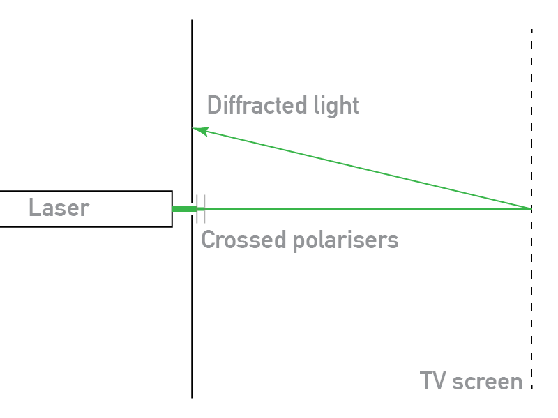
To get a more accurate measurement of the diffraction angles, I needed to know the displacement of the reflected light relative to the incoming light. The configuration I imagined was something like this:
I cobbled together, after finding some card, sellotape and blu-tack, the following:

After shining my contraption on the TV, I snapped several images like this:

Those 4 dots around the edges correspond to the diffracted streaks in the original image. Because the laser light is (approximately) monochromatic, we get diffracted dots rather than streaks.
Without a willing assistant in my endeavours, I only managed to take pictures at an oblique angle. To correct for this, I applied a a projective transformation to the image to flatten it out as if the picture had been taken on-axis:
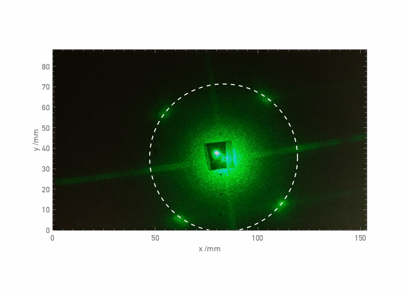
The circle marks a radius of 36mm from the centre of the diffraction pattern, and shows that the four spots diffract at the same angle. If I plot the image intensity along a diagonal line through the two spots, it looks like:

The standard equation for diffraction gratings states that the angle 


I was standing around 35cm from the TV screen for these photos, which plugging in to the above means the diagonal structures are around 5 microns in size. This is far too small, by a factor of 100, to be caused by the pixels (did I mention the TV is really big?), so must be caused by something else. Perhaps some structure in the matte plastic coating in front of the display? If anyone has an idea, please mention in the comments.
Theory
For the sake of completeness, we can also derive what we expected the diffracted light to look like, under a set of simplifying assumptions. Assuming that the pattern on the TV has a sinusoidal pattern of wavelength 


The amplitude of light on the card 

where 

where the paraxial approximation was assumed. Calculating the intensity, i.e. 
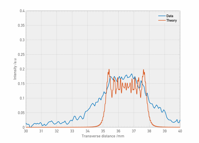
This doesn’t look too bad, but does still require a small feature size. For comparison, modelling different laser sizes and feature sizes generates the following plots:


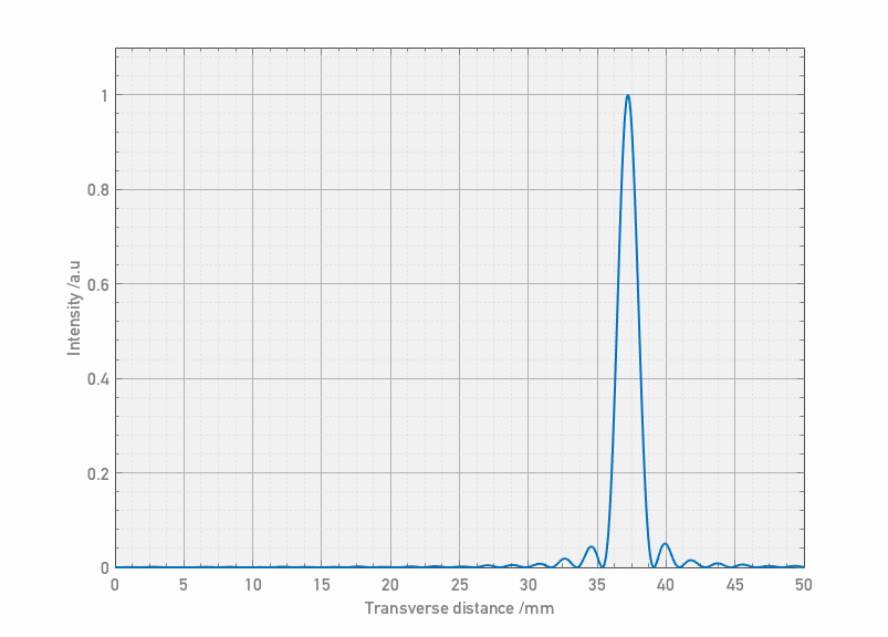

The best agreement is therefore a very small feature illuminated by a large laser spot. As I said before, any ideas – let me know!

Be careful with dodgy green lasers. Some emit dangerous amounts of IR.
https://www.technologyreview.com/s/420214/the-danger-of-green-laser-pointers/
LikeLike
Thanks for the warning. I was aware of this, it might be interesting in the future to compare the 532nm and 1064nm output on a spectrometer.
LikeLike
From taking apart some discarded large screen televisions I have found that there is a large fresnel lens in front of the pixel plane. The lens is a thin sheet of clear plastic the size of the screen. I am not sure but I believe it is there to make the screen brighter for viewers who are on-axis. There are you-tube videos of people using these in the sun to create hot spots that are very hot (and potentially blind themselves). I suspect that you are diffracting off the steps of the lens. You might try masking off all but a corner and see if the structure has a lower frequency in that corner as a fresnel would.
LikeLike
Interesting possibility! From what I can read it seems these were only used for rear-projection TVs. However, if there were a lens and it was composed of two sets of orthogonal linear grooves, that would explain the 4-fold symmetry. I’ll have to see if there’s a slight difference in the diffraction pattern between the centre and the edges of the display. Thanks!
LikeLike
Hey,
I am making an animation for children and it involves light reflecting colours and your image is perfect for this effects shot I’m trying to pull off, could I have your permission to use it? I will credit the source to you under your username or real name 🙂
George
LikeLike
Hi George,
Sure, no problem. If you’d like to credit me, my full name is Jason Cole.
Cheers,
Jason
LikeLike
wow, i was high, took a picture, saw that happening, went on Perplexity Ai to ask why this phenomenon was appearing. And it sent a link to this page. Now i felt like i just attended a physics class on optics.
LikeLike